The Golden Rules for Optimizing DC-AC Ratio in PV Power Plants

What is the DC-AC Ratio?
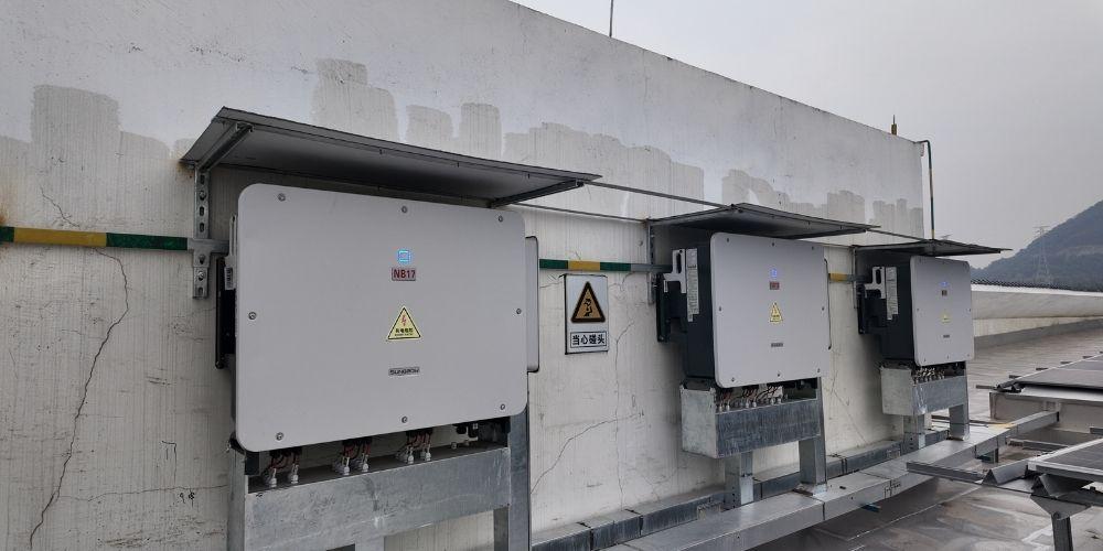
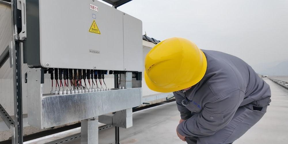
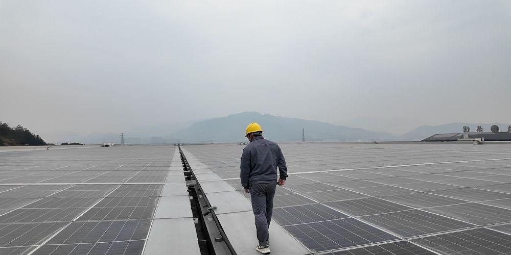
In the design of PV power plant systems, the ratio between the installed capacity of PV modules and the rated capacity of inverters, i.e., the capacity-matching ratio, is a very important design parameter. The configured capacity of the inverter in the PV power generation system should be matched with the installed capacity of the PV array, and the maximum DC input power allowed by the inverter should not be less than the actual maximum DC output power of the corresponding PV array, i.e., the DC-AC ratio should not be more than 1:1, which is usually referred to as “overmatching” when the capacitance ratio is more than 1:1.
Key Benefits of Optimizing the DC-AC Ratio
Enhance inverter utilization and reduce kWh cost
The potential capacity of the inverter can be fully tapped through over-allocation design (i.e., DC-AC ratio >1).
Considering that the light is not enough, the performance of PV panels decreases after a long time, and the temperature fluctuates, a reasonable adjustment of the configuration can make up for the loss of power generation. In this way, the inverter can run closer to full load, and the power generation efficiency of our entire PV system will naturally go up. For example, in the period of sufficient light, the module power may exceed the rated power of the inverter, but the inverter usually has 1.1 times the long-term overload capacity, then the over-allocation of the module can effectively fill the inverter's power gap.

Optimizing String Voltage & Extending Generation Hours
Overloading aligns the string voltage with the inverter's MPPT (Maximum Power Point Tracking) optimal range.
Case Study: For a 20kW inverter with an MPPT range of 430–850V, increasing the ratio from 1:1 to 1.2:1 reduced string voltage from 738V to 574V, closer to the ideal 640V midpoint—minimizing voltage-related losses. This also extends daily operation by 0.5–1 hour through earlier startup/later shutdown.
Offsetting System Losses & Smoothing Output
DC-side losses (soiling: 3–5%; cabling: 2–3%; module degradation: ~1% first year, ~13% over 30 years) are mitigated by overloading, keeping the inverter input near rated power. Higher ratios also stabilize output fluctuations, improving grid compatibility.
Industrial Application: In commercial rooftop PV, high DC-AC ratios reduce grid voltage anomalies from power swings, cutting penalty risks while boosting self-consumption ROI—a critical feature for distributed generation stability.
Factors Influencing DC-AC Ratio
PV modules rarely operate at nameplate capacity due to:
① Low irradiance
② High ambient temperatures
③ Soiling/dust (3–5% loss)
④ Suboptimal tilt/azimuth (minimized with trackers)
⑤ Degradation (1% first year; 0.4%/yr for TOPCon)
⑥ String mismatch losses

Calculating the Optimal DC-AC Ratio
While higher ratios extend full-load hours and reduce grid intermittency, excessive overloading wastes module capacity and land resources. The optimal balance minimizes CAPEX without curtailing energy yield, maximizing IRR.
Site-Specific Resource Assessment
Model local irradiance/temperature/wind data with module coefficients (e.g., derate by 5–8% in humid climates for conservative ratios).

High-Performance Equipment Selection
Pair high-efficiency, low-temperature-coefficient modules (e.g., bifacial glass-glass) with inverters featuring wide MPPT ranges and overload tolerance.
Example: A project using 182mm modules and string inverters increased its ratio from 1.2 to 1.4, achieving 3% higher efficiency and a 1-year faster payback.
Dynamic Optimization & Monitoring
Deploy smart SCADA to track performance and adjust ratios post-deployment.
Case Study: One plant restored a degraded 1.0 ratio to 1.2 by adding modules, boosting output by 4%.